Show Posts

This section allows you to view all posts made by this member. Note that you can only see posts made in areas you currently have access to.


Topics - SharpEars

Pages: [1] 2
1
Towards the end of the article at:

https://support.chaos.com/hc/en-us/articles/11905001704977-New-Volume-Resolving-in-Corona-1

..., under limitations, it says:

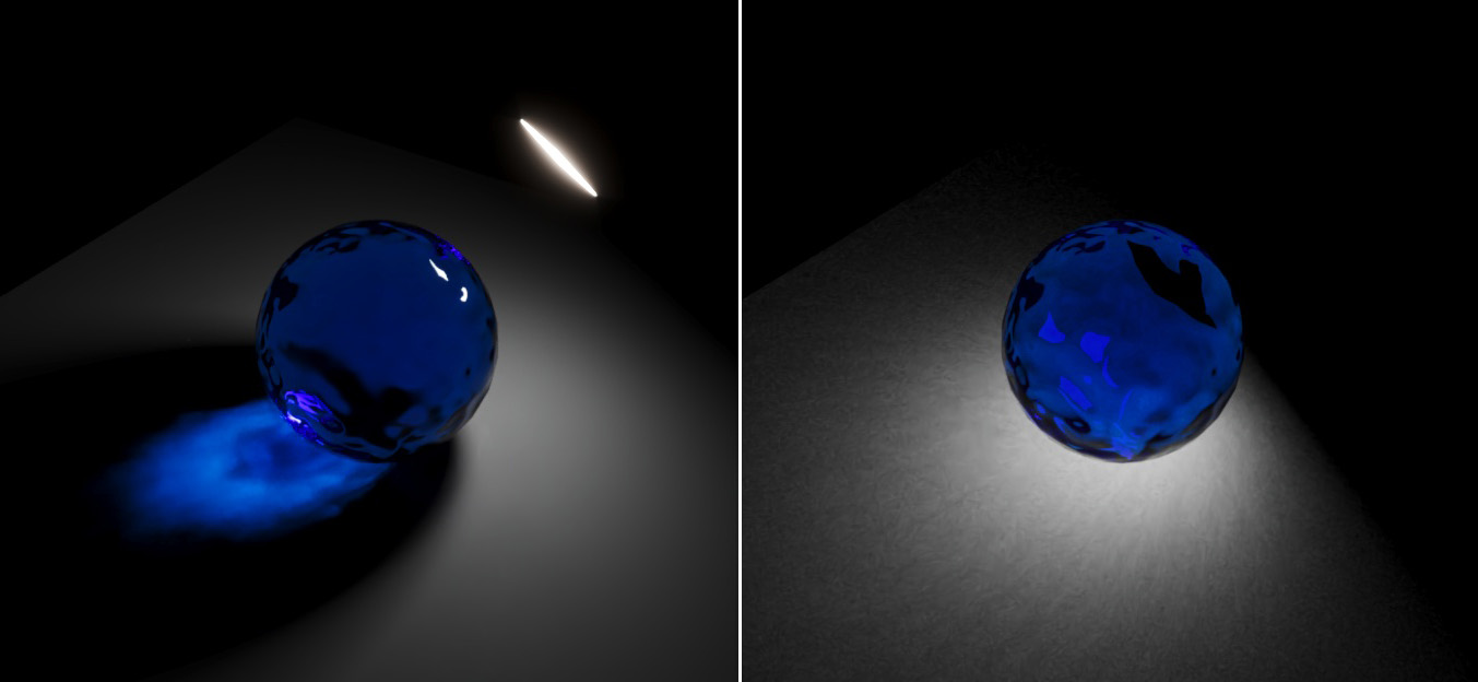
If a light is placed inside a medium, the caustics solver (Max | C4D) will ignore the absorption of the medium for caustics generated outside of it. Observe how the blue glass ball is casting non-blue caustics when the light is inside it.

and provides an example:


Is this something you guys are working to address in time for the release of Corona 10? It seems like a pretty large shortcoming.


2
There appears to be no way, that I have been able to figure out, to adjust the brightness and blur of reflections of a transparent surface, without changing the transparency as well. I am not talking about breaking “Energy Conservation” here, quite the opposite actually.

I would just like the ability to _decrease_ the brightness and increase the roughness of reflections without completely screwing up the refraction/absorption settings in the process.

With the “old” material, you could adjust the reflection settings independently (both color and glossiness), making it as rough and dim as you want dependent on the lighting and other scene objects.

With the new physically based material, when creating a fully transparent material (or even mostly transparent with little roughness) with maybe slight amount of absorption, reflections, especially of bright lights, tend to be super bright and razor sharp, dominating the material’s appearance and not giving the refractive properties a chance to show.

Perhaps what I am asking for is “bias” and the new material is supposed to move in the unbiased direction, but consider a good camera lens. It is coated with an anti-glare material that actually makes more light go through the lens, while reducing reflections from the lens elements’ surfaces. Clearly this is possible in the physical world! With Corona’s new material, sure there is a coating feature, but it sits on top of the horrid unchangeable reflections already present in a transparent material and can only add to “obscure” things further.

I haven’t found any way to tone reflections down (as in less bright via say a gray color instead of pure white) or blur them, while maintaining a good clean sharp transparency for a material.

Any tips short of masking/compositing?

BTW, node material doesn’t help here, because reflections get pulled in from the Directly Visible slot and do not get overridden by the reflection settings of the material connected to the Reflection socket. I don’t know if this is a bug or not, but in any case the material itself should allow for reflection adjustments (in terms of both color/brightness and roughness/glossiness) for refractive materials.

3
[C4D] Daily Builds / New Corona Physical Material and Metals
« on: 2021-02-21, 21:13:22 »
So in trying to use the new Physical Material to form metal surfaces, I've noticed the following limitations (either in the material itself or my understanding of how it works). Everything discussed below is with the Metalness Mode set to Metal

#1.
In Metal mode, our ability to control IOR gets disabled. Now, my understanding is that IOR is now controlled indirectly via Base Layer color and Roughness/Glossiness.

But, different metals have different Fresnel curves for reflection. For example, compare the Fresnel curve for Bronze with the Fresnel curve for Copper. This can be easily done in the Corona Node Material Editor:

Steps:

1. Create two Fresnel Shaders (New Shader/Fresnel)
2. Turn on Physical in the properties for both and set the Preset for one to Copper and for the other to Bronze.

Compare the resulting gradients.

Attached is an image showing four such gradients for Copper, Bronze, Iron, and Nickel.

Although it is true that their colors are different, the Fresnel curves for the four metals are vastly different. Compare for example the Iron curve with the Nickel curve.

So, my point is that with the inability to supply a proper Fresnel curve for our metal, we have no control over the type of metal we are trying to represent.

#2.

Taking this a step farther, it would be nice to enter the Red, Green, and Blue n/k value separately, since they are not necessarily the same for metals.

For example, SigerShaders has a nice free Complex Fresnel plugin for 3ds max that takes the Normal Incidence (n) and Extinction (k) values for each of the three primary colors to come up with a Complex Fresnel curve, that they have created based on Vlado's Complex Fresnel OSL shader code at: https://docs.chaosgroup.com/display/OSLShaders/Complex+Fresnel+shader (See the second attached image for its UI).

Can something like this be done for Corona for Cinema 4D, to make metals render more realistic?


4
I cannot for the life of me figure out how to get Cinema 4D noise shaders to working inside basic glass. For example, let's say you are making a basic marble (the sphere variety that kids play with, not the stone).

You start with a sphere and place on it a basic Corona Physical Material with the following changes from default:

Base Layer - Roughness value is changed from 75% to 0%
Turn on Rerfraction - (no changes to defaults)

OK, we now have a simple glass sphere. Now, the goal is to get a 3D Cinema 4D Noise shader inside the glass and not just on its surface.

I will be using the following Noise Shader and settings for this task:

Noise: Hama
Color 1: Pure Black (RGB: 0,0,0) (Should be the default)
Color 2: Pure White (RGB: 255,255,255) (Should be the default)
Space: Object
High Clip: 5% (To make the lines sharp and well defined, helping us determine whether they are on the surface or actually inside the object)
Everything else set to the default

OK, now if I stick the above Shader into the Refraction texture, I get noise on the surface of the glass sphere and not inside of it. This is true regardless of the Space property inside the shader (I tried them all going one by one from UV-2D to raster, and Object is the correct setting for 3d noise, so I settled on that).

Lesson learned: Putting a 3d noise shader into the Refraction texture slot only affects the surface of the object (i.e., sphere) and not its inside

Then, I tried to see if maybe turning on Volumetrics and placing that same Shader into the Absorption Color Texture slot would cause the inside volume of the sphere to take on the noise. (Mix mode was left at Normal and mix strength at 100%. The color was left at a default of 50% gray and is disabled in any case when the Texture slot is filled).

There was no change, the noise only affected the outside of the sphere and the result is attached.

I can't for the life of me figure out how to get the noise to appear, in 3D inside the sphere and not just on its surface.


5
I am referring to the type of silicone tubing showin in the attached pictures (soft milky tubing and other soft white or off-white shapes made out of milky translucent silicone).

Here is a good video showing it in use, which is helpful to see its translucent/transparent characteristics when fitted on to objects (especially starting at around 1:15 into the video): https://www.youtube.com/watch?v=Jq55YGcunrg

I am not sure if this is a good case for SSS, or if it requires full transparency and a Volume material. If anyone has created anything like this and/or knows giw a material that has these characteristics can be created, I'd appreciate the details.

6
Let me see if I can describe the scenario (latest Corona 5 in use with 3ds max):

You have a scene with a small spherical light, say 1 cm in size and which has no red component (e.g., RGB=0,96,255). It is a pretty strong light causing overexposure in the scene when viewed through the camera.

In front of the light (from the perspective of the camera), you have a glass hemisphere shell (i.e., imagine creating a 3-4 cm (in diameter) half-sphere (removing the flat bottom) and then using a 1-2 mm shell modifier on it, to create a fairly thin glass shell with an IOR of 1.5). Some details about the glass material are that it is blue in color , no diffuse (i.e., RGB=0,0,0, medium-blue reflection containing no red component and (RGB=0,10,160), a very light blue refraction containing no red component (e.g., RGB=0,10,255) and a glossiness of say 0.75 (not thin and no caustics).

So to use ASCII art you have this:

o)      >=#      (The 'o' is the light, the ')' is the hemisphere, and the >=# is the camera looking at it.)

In this very simple scene, the result is that the rendered light shining through the glass appears red or has an extremely strong red cast, even though there is no red component in the light source, or any parts of the material used for the glass.

So, it seems that Corona, when there is overexposure of blue, is adding a lot of red to the scene.

8
Maybe I am missing something, but is there a standard set of pre-built common materials (e.g., glass, metal, wood, plastic, etc...) for Corona for C4D that can be downloaded like there is a for 3ds max?

9
Here is a sample real world image:


What would be the best approach to producing these sorts of glowing LEDs with bleedover to adjoining LEDs due to bloom/glare?


10
So, a typical workflow:

You render with light mix and tweak light color and intensity. Then you take the tweaked values from the VFB LightMix and transfer them to the lights themselves. The problem is that the color as displayed in the VFB LightMix (color select dialog) does not match the color shown in 3dsmax CoronaLight modify panel direct color entry (dialog), when the HSV color values are identical.

To reproduce: Set an HSV value for a light in 3dsmax (modify panel) that has its own light select element. Set the same HSV value in the VFB LightMix. One is brighter than the other - they don't match exactly and they should. I am not sure if gamma is in play here or what, but the same HSV values should produce the same colors between the VFB LightMix and the 3dsmax CoronaLight modify panel direct color settings.

11
I am pointing out this one also, because this is critical and foundational information, especially for new Corona users:

When tweaking the output noise, the following suggestions are given at
What are the best render settings?
:
...
If you are dealing with strong noise caused by direct light, increase Light samples multiplier
See: How can I tell whether noise comes from direct or indirect light?

If you are dealing with strong noise caused by indirect light (GI), increase GI vs. AA balance
See: How can I tell whether noise comes from direct or indirect light?
...

The statement underlined is incorrect. Increasing the GI vs. AA balance will not affect the ratio of direct to indirect sampling per pixel. It may help slightly with both direct and indirect lighting, by marginally reducing the number of AA samples. The correct statement should be to decrease the Light samples multiplier which controls the direct/indirect ratio, thus providing more samples to indirect light by reducing the number of direct light samples (per indirect sample).

12
Is the "Filmic Highlights" setting applied pre-AA or post-AA? I just discovered that this setting does a very good job of reducing blown-out highlights (e.g., speculars). The big question is whether or not this setting can help with anti-aliasing high contrast transitions between dark and bright pixels in a manner similar to clamping. I ask because "Filmic Highlights" only affects the brightest parts of the scene (in the same way that Whites can be selectively toned down in Photoshop, without affecting darker pixels). Clamping, on the other hand, seems to indirectly affect all pixels in the scene, by reducing reflections and GI from very bright light sources. I much prefer Filmic Highlights to Clamping, in general.

13
Reading the documentation at the Fresh Desk for one of the more difficult concepts in Corona to wrap one's head around, What is GI vs. AA balance?, I noticed contradictory information. Namely, at the top we have the statement that:

If "Light samples multiplier" is set to 2 and "GI vs. AA balance" is set to 16, this means that 16 GI samples and 32 direct light samples will be used for each pixel per pass. This implies that:

32 = 16 ⋅ 2   # Or more generally:
Direct_Light_Samples = GI_VS_AA_Balance ⋅ LSM


Then further down the page, we have:

Example 3
GI vs. AA = 64
LSM = 0,25
64 samples are used for GI and 16x0,25=4 samples are used for direct light. There is visibly more noise in direct light pass than in GI pass. This implies that:

4 = 16 ⋅ 0,25   # Or more generally:
Direct_Light_Samples = 16 ⋅ LSM    # i.e., the GI vs. AA balance setting of 64 has no affect on the pre-adjusted "# of direct light samples" starting setting, which is fixed at 16 and cannot be changed by the user


Only one of the above can be correct. Which one (and please update the freshdesk to reflect the correct answer)?


14
[Max] I need help! / Ideas for a realistic spherical light
« on: 2017-02-13, 16:23:38 »
When one creates a spherical or disc light and that light is directly visible or gets reflected off of a very smooth reflective plane (or sphere) the light looks like a uniformly bright circle having one blown out color (e.g., white). This is because light emanates from the polygons that form the surface of the spherical light along their normals. So, I get something like this:


Another example with a disc light, which is completely blown out along its entire surface area. Notice also the very tight blown out reflection of the light on the ground. There is a little bit of high intensity falloff, but not much. The majority is low intensity falloff. But, in any case, the light shape itself when seen directly through the camera is solid white:


What if I want a spherical or disc light source of say six inches in diameter, but only want a one inch diameter sphere (circle for disc) inside of it to generate the vast majority of the light. Over the remaining five inches towards the surface (edge), the light should decay in brightness when seen in a reflection, basically forming a spherical (circular) gradient from a one inch hot spot in the center to just a light glow at the six inch point at the surface (edge). The entire light sphere/disc should be visible in a mirror reflection as a circular gradient - I am not talking about a simple point-light falloff here.

For a spherical light, I could put a one inch bulb into a six inch (smoked) glass sphere (hollow or solid), but this would probably astronomically increase render times, cause a crap-ton of noise in the render, generate undesired internal reflections and GI (maybe?) if the sphere is hollow, not to mention any issues stemming from the fact that the material may overlap (in the case of a solid sphere) the light source. So, as far as I know this is generally frowned upon as a viable solution. I don't even have bad ideas for what to do with a disc light to get a light gradient.

So, what are some ideas for accomplishing this in a reasonable manner with Corona?

Here is a not so great sample image. The highlight in the middle is a little too tight and the light decay does not reach the outer part of the bulb like I want, but you get the idea:


Taken to the other extreme, a nice gradient decay from a central hot spot which in this case is too small:


15
At How to set limit for rendering? - 3ds Max in the Corona Render FreshDesk, there are instructions on when a render should end. The third item states:

Quote
3. Enable Noise level limit for rendering:
go to Render Setup > Scene > General Settings > Progressive rendering limits, set Noise level limit other than 0

However, the instructional image and red outline box below the text does not show a Noise Level Limit setting, because (I think) this is an old image of this dialog box before the setting in question was added. The image should be updated to show the current state of the dialog box with the Noise Level Limit setting included and the red highlight rectangle extended accordingly.

Pages: [1] 2